Speaker Impedance Wiring Diagram

Rj11 Socket Wiring Diagram Australia, How to punch down an RJ11 Telephone Jack, 6.36 MB, 04:38, 387,634, CableSupply.com, 2009-08-05T00:16:07.000000Z, 19, Rj11 Socket Wiring Diagram Australia | Computacion, Redes de computadoras, Computadoras, www.pinterest.com.mx, 728 x 783, jpeg, rj11 wiring rj45 diagram cable ethernet usb jack pinout adapter cat5 female male convert using rs485 cat wires code socket, 20, rj11-socket-wiring-diagram-australia, Anime Arts
Two 8 ω voice coils in parallel, 8 ω ÷ 2 coils = 4 ω. Four 4 ω voice coils in parallel, 4 ω ÷ 4 coils = 1 ω. Four 8 ω voice coils in parallel, 8 ω ÷ 4 coils = 2 ω. If your speakers are of different impedances, there is a mathematical formula to determine the total parallel impedance.
Below, the diagram on the left shows four 4 ω speakers making a 16 ω cabinet. The diagram on the right shows four 16 ω speakers making a 4 ω cabinet. An easy solution is to draw out a diagram to avoid confusion. This tool handles that part for you. Wiring configuration for 2 speakers in parallel. Two 4 ohm speakers = 2 ohm load. Two 8 ohm speakers = 4 ohm load. Two 16 ohm speakers = 8 ohm load. Wiring configuration for 2 speakers in series.
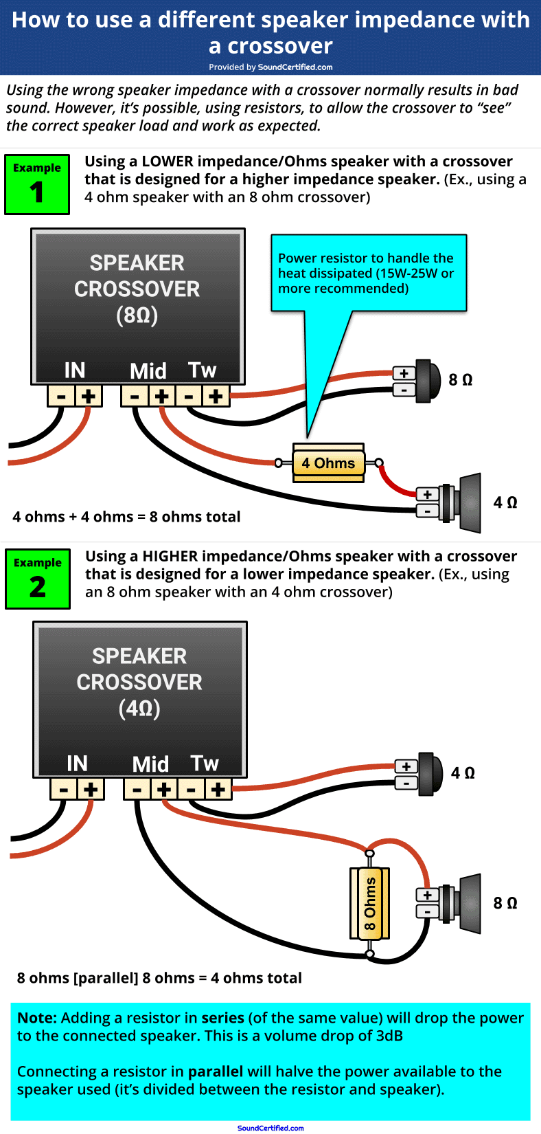
What Happens If I Use A Different Impedance Speaker On A Crossover?

Low Impedance Speaker Wiring for 4/8 Ohm Systems | TechLogix Networx
How To Tell The Impedance of A Speaker - A Guide For Everyone

Can you replace two 16 ohm speakers in a combo amp with 8 ohm speakers as long as the impedance
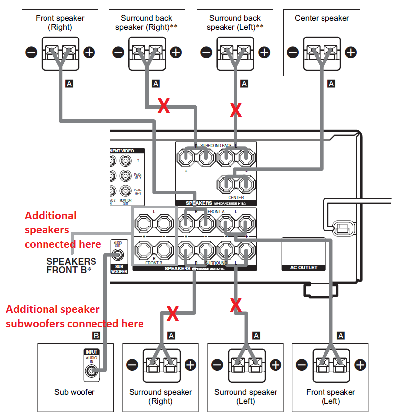
The Speaker Wiring Diagram And Connection Guide - The Basics You Need To Know

Parallel Speaker Impedance | Wiring Diagram

Volume Controls In-Wall Stereo Volume Control Switch with Impedance Matching for Speakers 100W

Loudspeaker impedance measurement using a multimeter and 2 resistors
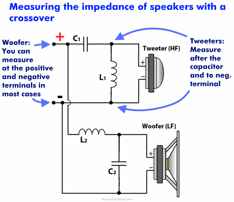
audio - Calculating impedance in a two-way speaker crossover - Electrical Engineering Stack Exchange
